How to Add 3D Vision to Your Robot with a LiDAR Matrix Sensor
Introduction
Imagine your robot can see the world in three dimensions—not just how far away something is, but where it is in space. That’s the power of a LiDAR matrix sensor. Unlike a standard time-of-flight (ToF) sensor that measures distance to a single point, a matrix sensor packs 64 individual zones into one tiny package, creating a 2D map of distances from 2 cm to 3.5 m. This guide walks you through adding such a sensor to a 3D-printed tank robot (like the one named Zippy) powered by an ESP32. By the end, your robot will be able to detect obstacles, see the floor ahead, and move autonomously. Let’s get started.
What You Need
- LiDAR matrix sensor (e.g., VL53L5CX) – 8x8 multi-zone range sensor
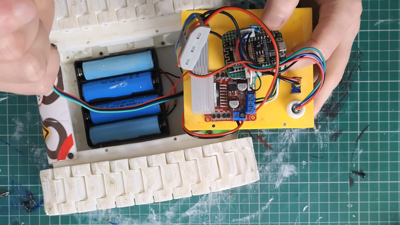
- Robot platform – 3D-printed tank chassis with treads (or any mobile robot base)
- Microcontroller – ESP32 (or similar with I²C support)
- Jumper wires – female-to-female for I²C connection
- Breadboard (optional) for prototyping
- LiPo battery or USB power bank for ESP32
- Computer with Arduino IDE or PlatformIO
- USB cable for programming ESP32
- Mounting hardware – screws, standoffs, or 3D-printed bracket for sensor
- Large Language Model (LLM) (optional) – to help generate initial code
Step-by-Step Guide
Step 1: Assemble and Prepare the Robot Platform
Start with your robot chassis. If you’re building Zippy (a popular 3D-printed tank bot), print all parts and assemble the treads, motors, and mounting plates. Ensure your platform can move forward, backward, and turn. This guide assumes you have a working robot that can accept control inputs (e.g., via serial or Bluetooth) before adding the sensor.
Step 2: Mount the LiDAR Matrix Sensor
Position the sensor at the front of the robot, angled slightly downward. The VL53L5CX has a 45° field of view, so tilting it about 15–20° helps it see the floor in front of the robot. Use a 3D-printed bracket or double-sided tape to secure it. Important: Mount the sensor so that the bottom rows of its 8x8 zone array point toward the ground. In Zippy’s case, about half the rows see the floor—this is actually good because it lets the robot detect drop-offs or obstacles on the ground.
Step 3: Wire the Sensor to the ESP32
The VL53L5CX communicates over I²C. Connect the following:
- Sensor VIN → ESP32 3.3V (or 5V if your module has voltage regulator)
- Sensor GND → ESP32 GND
- Sensor SDA → ESP32 GPIO 21 (default)
- Sensor SCL → ESP32 GPIO 22 (default)
- Optional: Sensor XSHUT → ESP32 GPIO (for power management)
Use female-to-female jumper wires. Double-check polarity before powering up. If you’re using a breadboard, insert the sensor module and run wires to the ESP32.
Step 4: Power Up and Verify Connection
Connect the ESP32 to your computer via USB. Open the Arduino IDE or PlatformIO and upload a simple I²C scanner sketch to confirm the sensor’s address (usually 0x29 or 0x30). You should see the address printed in the Serial Monitor. If not, check wiring and power.
Step 5: Write or Generate the Sensor Code
To read the 64-zone distance data, you’ll need a library (e.g., VL53L5CX by STMicroelectronics or a community one). You can write the code manually or—as Mellow Labs did—use an LLM to generate most of it. The LLM can produce a sketch that initializes the sensor, reads the 8x8 array, and prints distances. Expect several iterations: the first LLM output may need tweaks to handle data rates or I²C timing. A handy trick is to decimate the data—only read every other zone or every other measurement cycle—to reduce processing load on the ESP32, since the full 64 zones at 60 Hz can be overwhelming. Mellow reduced the active zones further to free up computing power for motion control.

Step 6: Calibrate and Test the Sensor
Once the code compiles and uploads, place the robot on a flat surface. Open the Serial Plotter or use a simple Python script over serial to visualize the 8x8 distance map. Check that:
- The top rows (pointing forward) return large values when far from obstacles.
- The bottom rows (pointing to floor) show consistent short distances (e.g., 10–30 cm).
- When you move an object in front, the corresponding zones change values.
If the floor is too close or too far, adjust the tilt angle. If data seems noisy, try averaging multiple readings per zone. Zippy’s design showed the floor on about half the rows – that’s normal. Remember: seeing the floor means the robot can detect ledges or stairs, which is a feature, not a bug!
Step 7: Integrate Sensor Data into Autonomous Navigation
Now it’s time to close the loop. Write a control algorithm that uses the distance map to make decisions. For example:
- If any front zone reads < 30 cm, stop or turn.
- If a floor zone suddenly shows a large distance (hole), back up.
- If the left side is blocked but right is clear, turn right.
Combine sensor readings with motor control code. Start simple: make the robot drive forward until it sees an obstacle, then reverse and turn. With the 64-zone data, you can even implement wall-following or corridor navigation. Remember to tune the decision thresholds based on your robot’s speed and braking distance. Mellow’s robot ultimately gained basic obstacle avoidance using this sensor, proving that even with decimated data and some floor-viewing zones, the robot can navigate effectively.
Tips for Success
- Don’t worry about wasted zones. If the bottom rows see the floor, that’s useful for detecting drop-offs. You can also software-ignore them if you prefer.
- Use an LLM iteratively. Let it write the boilerplate, then manually adjust sensor settings and add your own logic. Expect several rounds of debugging.
- Decimate wisely. Instead of reading all 64 zones every cycle, read a subset (e.g., every other row and column) or only update every other loop. This gives the ESP32 more time for motor control.
- Calibrate the floor distance. Measure the sensor height above ground and set a threshold. If a zone reads higher than that threshold, it’s likely an obstacle (or a hole).
- Test in good lighting. Time-of-flight sensors work in various lights, but strong sunlight can interfere. Test indoors first.
- Borrow existing code. Check community libraries and examples for the VL53L5CX. Adapting is faster than writing from scratch.
- Add a warning LED. When the robot detects an obstacle nearby, blink an LED – it helps during debugging.